Step 1: Remove Monitor Casing
To remove the monitor case, turn it screen-side down and locate the (2) screws
holding the back half of the casing to the front (they are located on the
sides of the case). Once these screws have been removed, there are (2) plastic
tabs, one on each side, that you need to pry loose. These tabs are sometimes
stubborn, so apply a fair amount of pressure while pulling the back of the
case away from the front. With the back casing off, your monitor should look
like the following image:

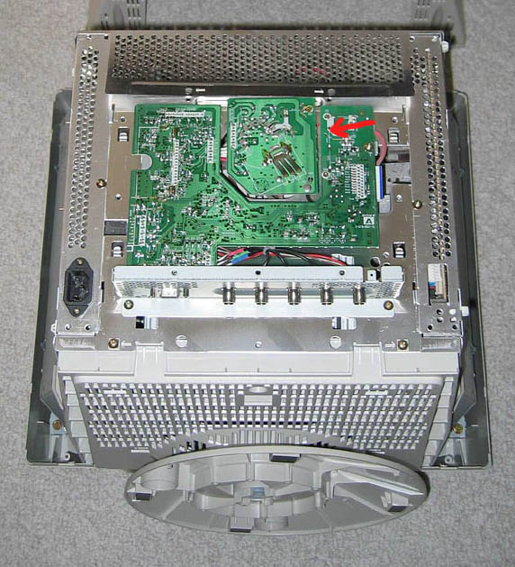
Step 2: Remove RF Shielding
Now you need to remove the RF Shielding (metal mesh) that is covering the
circuit board on the rear of the monitor. There are a number of small screws
around the edges of this shielding that just need to be removed. Once the
shielding is off, you should be looking at the following image. Notice the red
arrow drawn in the upper right hand corner of the board, this is the area we
will be working with.
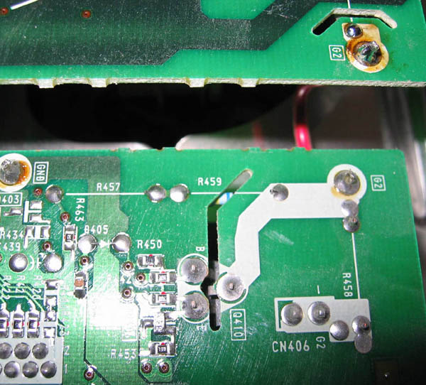
Step 3: Locate R459 Resistor and Remove
In the upper right corner of the circuit board, you should see a label
"R459" between 2 solder points. The following image has been rotated
90 degrees clockwise from the previous image. The R459 resistor is on the
underside of this board is relatively hard to get to, but you need to disable
it by breaking the circuit. The best way I have found is just using a small
pair of wire cutters to snip one of the resistor legs. Make sure the circuit
is cleanly broken and not touching anywhere. For reference, the original R459
resistor is supposed to be rated at 10 MOhm. A number of people have left the
R459 resistor intact and soldered an additional 10MOhm resistor in parallel
with it, creating an effective resistance of 5MOhm. However, the math becomes
a little more complicated when trying to vary your resistance value in this
scenario.
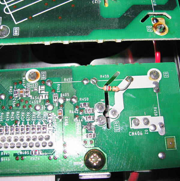
Step 4: Solder on New Resistor (4.7-6.8 MOhm)
You are going to need to buy a resistor in the 4.7-6.8 MOhm range (should cost
about 20 cents). The exact resistor you need is dependent on the severity of
the problem - but any value in this range should provide substantial
improvement. The general consensus is the lower the resistance, the darker the
result will be. Using the two existing R459 solder points, solder on your new
resistor. After you are finished, it should look something like the following
image:
Step 5: Reassemble the Monitor
Reattach the RF Shielding with the screws and then snap the back casing of the
monitor onto the front. Replace the two screws you removed and you are
finished. After turning it on, you will need to adjust the brightness and
contrast controls because the monitor will be much darker (and you should have
a nice black level).